Modifications to the IC211 and IC245
Published in VHF communications Nr 2 1982.
The introduction to this series of articles was given in Edition 1/82 of VHF COMMUNICATIONS.
This explained in detail why the dynamic range of transmitters must be as great as possible, and explained this with the aid of examples. A comparison of values measured on well-known commercial 2 m transceivers showed that there was a lot to be desired in this respect. Part 2 of this series of articles, which was published in Edition 1/82,gave a number of modifications to the TS 700.
In the TS 700 the problems were caused by undesired AM-modulation of the carrier. In ICOM IC211 and IC245, like in most other transceivers, the noise is caused by undesired phase- or frequency-modulation.
The measured noise sidebands of a number of IC211 and IC245 transceivers are given in Figure 1. The continuous lines show the measured values before modification,
and the dashed lines afterwards.
Transceivers A and B were measured both before and after the described modifications. In the case of transceiver C, the VCO was replaced by a high-quality (!), home-made oscillator.
The othertransceivers: D, E, F, and G were only measured before or after the modification.
Fig. 1: Sideband noise of various transceivers IC211/lC 245. Measuring bandwidth: 3 kHz.
The VCO of the transceiver series IC211 and IC245 exhibit the usual weakness of commercially available transceivers:
The varactor diode is fed via a 47 kiloohm resistor. The output of the phase comparator is low-impedance and has a relatively low noise component.
However, a considerable noise voltage is present at the varactor diode, which is caused by the leakage current.
This voltage has a 1 /f component, which causes a correspondingly varying voltage drop across this resistor.
The easiest solution to this problem is to feed the varactor diode from a low-impedance source, which can be easily achieved. It is only necessary to connect an RF-choke in parallel with the 47 kiloohm resistor.
After carrying out this modification, the noise sidebands will be considerably reduced, and the main component will now come from the phase comparator.
In order to suppress this noise, it is necessary to build-up a passive filter as shown in Figure 2, and to insert it between phase comparator and VCO.

Fig. 2: This filter should be installed between phase comparator and VCO
The filter shown has an output impedance of approximately 1 kiloohm at 10 kHz and will completely short out the noise caused by the leakage current.
It will also suppress the noise from the phase comparator sufficiently to ensure that it will have no effect on the noise sidebands.
The filter causes an additional phase shift in the control circuit which can lead to instability and poor lock-in characteristics. However, this phase shift can be compensated for by realigning the trimmer potentiometer in the active loop filter so that the control circuit locks in correctly.
There are various different versions of the IC211 and IC245 transceivers and this potentiometer is to be found in different positions in the unit.
In order to identify the correct potentiometer, one should study the circuit extract given in Figure 3.
It is designated R28 in this circuit, and often it is found that the best lock-in characteristics are obtained with this potentiometer adjusted to one of its limit positions.
The active filter should be soldered with short connections directly to the VCO-module, as can be seen in Figure 4.

Fig. 3: The circuit extract from ICOM shows where the potentiometer is to be found that allows the phase shift to be adjusted.
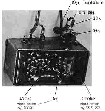
Fig. 4: This photo shows where the parts should be located
The VCO of many transceivers will have been modified already by the manufacturer. This is in the form of a RC-network of 470 ohms / 1 nanofarad, which will have been inserted into the sourcecircuit of the oscillator transistor.
These two components are accommodated on the conductor side of the PC-board, after breaking the required conductor lane.
Figure 5 shows this ICOM-modification, as well as the modification recommended by the author, in the form of a circuit diagram.
This can be seen from the measured sidebands of transceivers A, B, and E in FigUre 1. ICOM probably wanted to redUce the oscillator power with this modification in order to reduce the RF-voltage across the varactor diode.
This in turn will reduce the leakage current through the diode, and subsequently the voltage drop across the 47 kQ resistor.
After carrying out the recommended modifications listed in this article, the ICOM-modification will no longer be required, since the voltage source of the varactor diode will exhibit such a low-impedance for lower frequencies that the 1 /f component of the leakage current will not be able to cause any voltage drop.
Fig. 5: This partial diagram of the VCO shows both the ICOM modification, and the modification recommended by the author The manufacturer's modification reduces the values of the noise sidebands by approximately 5 dB when compared with the original state.
It should be noted that two components are somewhat critical:
The 10 microfarad capacitor should have a low leakage current, since such leakage currents can have a high noise component.
The author uses tantalum electrolytics. The RF-choke should be a good VHF-type, in other words, it should have a high Q so that it does not deteriorate the Q of the resonant circuit.
The inductance and capacitance values are not critical, since any detuning of the oscillator resonant circuit can be compensated for by correcting the core of L1.
A choke made from one layer of enamelled copper wire wound on a 1.5 mm diameter ferrite rod of 10 mm in length has been found to be very suitable.
The author has taken such chokes from transistorized VHF/UHF TV-tuners. A coil wound from a quarter wavelength wire (thin) would also be suitable.
A disadvantage of the recommended modifications should also be mentioned:
The lock-in time is increased for large frequency variations. This will be noticed as a short delay between transmit and receive when operating split frequency operation (repeater operation).
This disadvantage can be avoided by connecting a pair of IN4148 diodes across the 33 kiloohm resistor (dashed lines in Figure 2).
The author has not tested such diodes in amateur transceivers, but in a different application where fast locking was required. Such solution worked excellently.
For these diodes to work, the output impedance of the phase comparator must be much smaller then 33 k, which is the case for IC211 / IC245.
It is wise to connect an oscilloscope to the comparator output when all modifications are done.
The AC component of the output from the phase comparator should be below 0.5 V (peak), also when a considerable audio level is present at the built-in loudspeaker, or knocking at the transceiver to simulate mobile usage.
The RF-choke should be constructed in a mechanically stable manner, since a microphonic effect will be caused if its hot end is vibrated by a high pressure from the built-in loudspeaker, or during mobile operation.
The slow reaction of the phase control will then lead to an unreliable lock-in characteristic.
It is therefore advisable to glue the choke with an adhesive having good RF-characteristics (low tan delta).
The adhesive should be approximately 1 mm thick. It represents the dielectric of a stray capacitance, and if it is made too thin, the high capacitance, and high electric field strength in the dielectric will cause losses and thus increased noise sidebands.
Several dozen IC211/245 were modified according to this description in Sweden and Finland.
According to my knowledge, no problems have been encountered. The average improvement at small frequency spacings from the carrier is approximately 15 dB. This means that the described modifications reduce the interfering noise sidebands by the same value as would be the case when switching off a 300 W linear amplifier and operating the station, "barefoot" with only 10 W !
In the case of the IC211, an improvement of approximately the same value will be present in the receive mode.
This improvement is less pronounced in the case of the IC245 due to its simpler input circuit of the receiver.
|

