Although specifically for the IC-575, this modification should apply to both the IC275 and IC-475.
The early versions of the Icom IC-x75 rigs had Pass Band Tuning (PBT), a feature left off later models, but with minimal effort this feature can be retrofitted. An improvement in 2nd I.F. selectivity also results.
The PBTless models use the PBT potentiometer as a "Data Level" control which adjusts the level of the external audio input from the accessory socket on the back of the rig. The most obvious use for this is for a RTTY/packet modem. In my opinion the "Data Level" control does not need to be on the front panel because once it has been set correctly for a particular TNC etc. it should not require tweaking.
Interestingly, the "Data Level" pot is still a centre-detent type like the original PBT control. Examination of the schematic reveals that it's the same value, 10K, as the original. Furthermore, the PBT line from the D.A.S. unit is now connected to a fixed-value resistive divider, made up of two 4k7 resistors. Hmmm!
A comparison between the "old" schematic and the "new" schematic also shows that a ceramic filter, FI3, has been deleted from the newer radios, being replaced with a 0.0047uF capacitor. Other than that, everything else is still there. When you think about it, it's the obvious and cheap way out for Icom to remove this feature by making minimal changes to the design and to "hard-wire" the PBT to the centre position, rather than making major changes to its production run.
The "missing" filter
You will need to purchase a Murata CFJ455K5 filter. The specifications of this filter are;
| Centre frequency: | 455kHz |
| Bandwidth: |
2.4kHz @ -6dB |
| Passband Ripple: |
2dB |
| Input Impedance: |
2k Ohm |
| Output Impedance: |
2k Ohm |
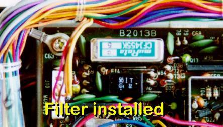
Picture 1 - The Murata filter fitted to the Main Unit PBA after the modification.
Modification procedure
- Remove all connections to the set, eg; power, antenna, mic, accessory leads etc.
- Remove the 9 screws holding on the bottom cover.
Position the radio so the front of it is towards you. All the mods are done to the Main Unit PCB (the largest PCB).
- Remove the six screws holding down the Main Unit PCB.
(Or is that seven??? I have a habit of losing the damn things!)
- Disconnect the coaxial lead plugged into J2 on the right hand side of the Main Unit PCB.
- Disconnect the internal speaker feed to J17, located at the rear right hand side of the PCB, next to the external speaker jack.
Disconnecting these two feeds will make it easier to turn the PCB over to gain access to the solder-side.
- Carefully pry the PCB loose. The "Ext Sp" and "Key" jacks on the back of the PCB make this quite awkward.
The PCB will need to move towards the front of the radio in order to clear the rear panel.
- When it's in the clear, the rear side of the PCB can now be flipped over.
- Remove C279 (0.0047uF). This is located front left - see picture 2.
- Remove the link near C279 designated as W159.
- De-solder the other nearby holes associated with the filter.
(These holes will be immediately obvious if you have a look at the pin-out of the filter). 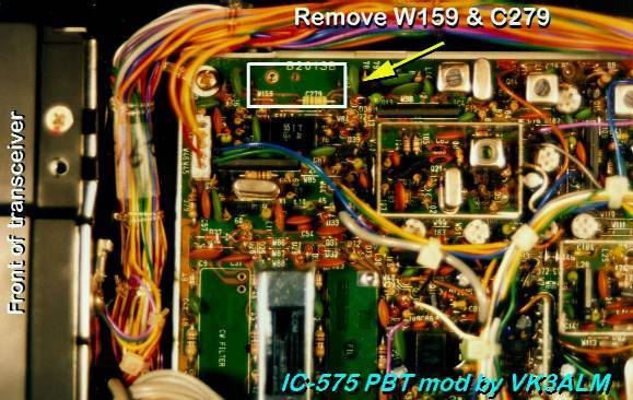
Picture 2 - Location of filter area on Main Unit PBA
- Solder the CFJ455K5 filter in position.
- Re-orientate the PCB back to its normal position.
- The blue wire going to the PCB just near J10 needs to be cut, preferably as close to the pin as possible.
J10 is located front left of the PCB, near where the filter was just installed. You will find this much easier to do if you temporarily remove the connector plugged into J10. This blue wire is the "PBTV" line, the Pass Band Tuning Volts line, and was fixed to +4 volts, ie; set for the centre of the "normal" passband. Now there are a number of ways of providing this line with the adjustable 0 - 8 volts that is required. I shall now describe the method I used - using the (waste of space) "Data Level" control.
- Disconnect the connector that goes to J20. This is the feed that goes off to the "Data Level" pot. Put this aside for now.
- De-solder and remove J20 from the PCB.
- In J20s place I mounted a vertical 10kohm trimpot - see picture 3.
The trimpot leads will need to bent in order to fit, and the wiper will need a small length of wire added to it so that it makes the distance to the hole in the PCB. 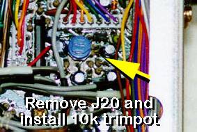
Picture 3 - 10k trimpot fitted to where J20 used to be. This allows you to retain the "Data Level" control, albeit a trimpot inside the radio.
- The Main Unit PCB can now be re-fitted and screwed back down.
Don't forget to reconnect the coaxial lead to J2 and the internal speaker feed to J17. This male connector is now used for connecting +8 volts, ground, and the PBTV line to the pot.
- So, on the "old J20" male connector we now need, matching the leads from the pot on the female connector;
Red (wiper) The blue wire (PBTV line)Braid (CW end) GroundWhite (CCW end) +8 volts There are many spots around the PCB to obtain +8 volts and ground from, but the easiest spot to access is IC15, a 4066. This is located just to the rear of the (big) 9.0105MHz crystal - see photo. Connect to Pin 14 for +8 volts and pin 7 for ground.
- To prevent shorts, tape over where you have soldered the wires to the (J20) connector.
Making use of these connectors, rather than cutting them off and soldering the wires directly to each other, improves access and serviceability to the Main Unit PCB, should that be required at a later date.
Alignment
It's not absolutely necessary to tweak anything but if you are fastidious about alignment and have an accurate Digital Frequency Meter, hook it up to the "test point" at R209, a 100R resistor. Those of you with an IC-575 Service Manual can refer to page 2-4 for PBT alignment.
Here is the procedure anyway;
20-1 With the radio receiving in the AM mode and PBT set to full CCW, adjust L17 for a frequency of 9.46830 MHz.
20-2 Centre the PBT control. Adjust R90 for 9.46500 MHz.
20-3 With the PBT still centred, change to USB mode and adjust R93 for 9.46650 MHz.
20-4 Change to FM mode. Adjust R95 for 9.46650 MHz. (Adjusting the PBT whilst in FM mode should make no difference to this).
21) Before you screw the bottom cover of the radio back on you'd better adjust the "Data Level" trimpot to suit your requirements.
Make sure you have reconnected the internal speaker feed to J17, the coaxial lead to J2, and the connector to J10.
22) Refit the bottom cover and screw in the nine screws.
23) Reconnect power and antenna feeds and confirm normal operation.
Checkout
Place the "new radio" into USB mode and note the enhancement of the highs at the CW end of the "Data Level" control, err make that the "PBT" control, and the enhancement of the lows at the CCW end of the control. Now, place the radio in the LSB mode and note the complementary effect.
Needless to say, any modifications done outside of an Icom service centre will no doubt void any warranties on the radio.
Having the PBT has been handy when trying to zero-beat TV carriers, although the bass response of the small internal speaker is not particularly good. A larger external speaker or headphones here will help. The poor bass response could be improved by increasing the value of C192, a 0.1uF capacitor in the audio line.
I feel the PBT feature would be more useful in Europe than it has proved to be over here in VK, for the simple reason; there aren't as many 6MX ops over here - even with Summer Es - so QRM from another nearby station is rare.
|

