Modification summary:
The "n" data to the 1MHz PLL needs to changed so as to introduce a 1, 2, 3 or 4 MHz offset.
Access to the PLL Unit is required.
There are many ways of achieving this, from a simple toggle switch to introduce a -4MHz offset to more elaborate schemes involving EPROMs and the like.
I must thank Graham, VK6RO, who originally published the idea (1982) of shifting the coverage down 4MHz to copy TV signals in the 46-50MHz range. It was Graham's idea that prompted me to create my own TS-660 mods in 1986, as detailed here. Although I reluctantly sold my 660 in 1996 I present the mods here to those who may be interested.
Bill of Materials:
1 x CMOS 4008 4-Bit adder
1 x 4 position miniature rotary switch
1 x 1N914 diode or equiv
2 x 10k ¼W resistors
hookup wire
veroboard
Band Truth Table (original coverage):
MHz D C B A  n     Notes 1) D=8  C=4  B=2  A=1

21  0 1 0 1  10          2) Logic is inverted

24  0 0 1 0  13

26  0 1 0 0  11

27  0 1 0 1  10

28  0 1 1 0   9

29  0 1 1 1   8

50  0 1 0 0  11

51  0 0 1 1  12

52  0 0 1 0  13

53  0 0 0 1  14
As you can see the "D" input to Q15 is always "0" and permanently tied low.
Band Truth Table (expanded coverage):
MHz D C B A  n   Offset from nearest band

20  0 1 1 0   9  -1MHz & -1n from 21MHz

21  0 1 0 1  10

22  0 1 0 0  11  +1MHz & +1n from 21MHz

23  0 0 1 1  12  -1MHz & -1n from 24MHz

24  0 0 1 0  13

25  0 0 0 1  14  +1MHz & +1n from 24MHz

26  0 1 0 0  11

27  0 1 0 1  10

28  0 1 1 0   9

29  0 1 1 1   8

30  1 0 0 0   7  +4MHz & -4n from 26MHz

31  1 0 0 1   6  +4MHz & -4n from 27MHz

32  1 0 1 0   5  +4MHz & -4n from 28MHz

33  1 0 1 1   4  +4MHz & -4n from 29MHz

46  1 0 0 0   7  -4MHz & -4n from 50MHz

47  0 1 1 1   8  -4MHz & -4n from 51MHz

48  0 1 1 0   9  -4MHz & -4n from 52MHz

49  0 1 0 1  10  -4MHz & -4n from 53MHz

50  0 1 0 0  11

51  0 0 1 1  12

52  0 0 1 0  13

53  0 0 0 1  14

54  0 0 0 0  15  +1MHz & +1n from 53MHz
You will need to access the "D" line as we now need to switch that as well.
(This may involve cutting a track or removing a link to ground - I can't remember which!)
Switching the offset in:
In order to switch in the offset I removed the 6.5mm Key socket mounted on the rear and replaced it with a miniature 4-position rotary switch. The switch was wired for;
- Normal
- -1MHz offset
- +1MHz offset
- 4MHz offset
You will note from the truth table that for both +4MHz and -4MHz we need to subtract 4 from the n-count anyway.
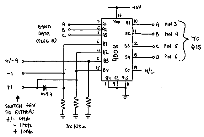
The adding & subtracting is achieved by using a CMOS 4008 4-bit Full adder.
Refer to the schematic below;
The original band data is fed into the "A" inputs of the 4008, and the offset switch is fed into the "B" inputs of the 4008.

Results:
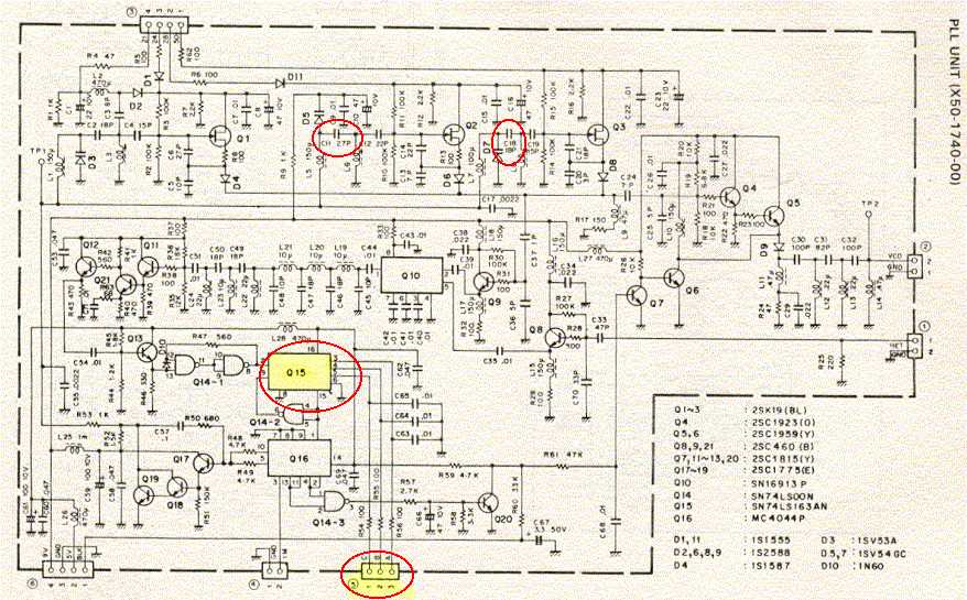
You may find that your VCOs (and there are three VCOs) don't remain locked over the entire range the logic is capable of. Improvements were made in my TS-660 by making the following changes;
- 28MHz VCO - Replace C11 (27pf) with 56pf
- 50MHz VCO - Add 22pf across C18 (18pf)
This scheme worked very well, and I added more features by upgrading to an EPROM based system. By using the "Hold" button and feeding TXB into the EPROM address lines as well as the band data and the offset data I introduced a "Repeater" and "Reverse Repeater" mode. This allowed me to run repeater mode without having to use both VFOs - very annoying! I could program the repeater output frequency into a memory and switch in the -1MHz offset when transmitting.
The complete PLL Unit Schematic:
Click on the picture below to see a larger image.

|
