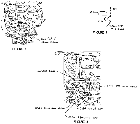
In some TS-940S below S/N 711xxxx, a "popping" or "clicking" noise may be heard when the squelch circuit is opened or closed. This may be more noticeable when an optional CW filter is installed. The following procedure will minimize the noise.
Parts required:
R194        560 Kohm 1/6 watt             RD14CB2C564J
R197        220 ohm 1/6 watt              RD14CB2C221J
R355, 356   220 Kohm 1/6 watt             RD14CB2C224J
C284        0.47 µF, 50V electrolytic      C90-0484-05
Procedure:
- Disconnect the power cord and antenna from the transceiver.
- Remove the top and bottom covers (16 screws).
- Locate the I.F. board on the bottom of the transceiver.
- Remove the 7 screws from the I.F. board.
- Carefully unplug connector # 17 (right side of optional CW filter) by prying up on the plug. Do not pull on the wires.
- Move the 4 wires (yel, org, brn, red) that run across the far side of the I.F. unit out of the way so the board may be removed.
- Carefully lift and rotate the board toward the left side of the transceiver to expose the foil side of the board.
- Using a small craft knife, cut the foil at the 3 points shown in figure 1. (top right corner of the board).
- Unsolder and discard resistors R194 and R197. They are mounted on the component side of the board and soldered on the foil side.
- Install a 560 Kohm resistor on the component side of the board as shown in figure 2. This resistor is now designated as R194.
- On the foil side of the board, add the 3 resistors (R197, 355, 368) as shown in figure 3.
- Add a small jumper wire as shown in figure 3.
- Add capacitor C282 as shown in figure 3. Observe polarity and insulate the positive (+) lead with shrink tubing.
- Carefully place the board in its original position (do not pinch wires) and secure it with the 7 screws.
- Plug in connector # 17. Move the 4 wires on the far side of the board back to their original position.
- Put the covers back on the TS-940S and secure them with the 16 case screws.
- Connect the antenna and power cord then test the transceiver for normal operation.

This is an optional change that may not be performed under warranty. Time required for this modification is 1 hour or less.
|
