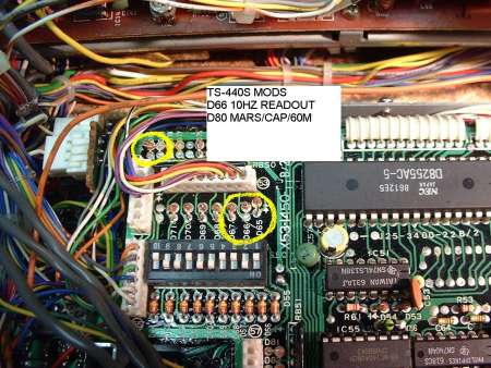
The TS440 is nice. Here's what I've found out about it that isn't in
the operation manual (in some random order):
Diode options: There are a bunch of configuration options controlled by
clipping or inserting diodes on the back of the control board. You get
to it by taking the top and bottom covers off (a bunch of silver
screws), loosening the front panel (4 flat-head silver screws, NOT the
black ones). Then you have:
   diode        controls                in              out (cut)
   -----        --------                ----------      ----------
   D65          mode confirmation       Morse           single beep
   D66          display resolution      100 Hz          10 Hz
   D67          memory protect          none            on
   D73          CW shift                800 Hz          400 Hz
   D78          WARC 24MHx band tx      disabled        enabled
   D79          WARC 18MHz band tx      disabled        enabled
   D80          General Coverage tx     disabled        enabled

Self-Test: You can run a rather complete test of the control logic by
the built-in "semi-self-test", a series of 56 routines. To run this,
turn the unit on whilst holding the AM and T-F SET switches pushed in.
It changes to the next test when you turn the VFO knob clockwise. Turn
the power OFF to reset the unit.
   Test         What it does
   ----         ---------------------------------------------------
     0          all positions in display light
     1          all segments in display dark
     2          all positions in display light
     3          all segments in display dark
     4          one digit lighted (rightmost)
     5          next digit lighted
     6          next digit lighted
     7          next digit lighted
     8          next digit lighted
     9          next digit lighted
    10          next digit lighted
    11          next digit lighted
    12          next digit lighted
    13          next digit lighted
    14          next digit lighted
    15          next digit lighted
    16          next digit lighted (leftmost)
    17          beeper sounds
    18          beeper silent
    19          all mode LEDs ON
    20          all mode LEDs OFF
    21          receive
    22          transmit
--------------------------------------------------------------------------
The following tests change internal signals. They are most useful if
you are trying to trace the circuits controlled by these signals.
You'll need a s service manual (or at least a schematic) to made reals
sense of these.
    23          Band select - all lines high
    24          BAND select - all lines low
    25          PD select - all lines high
    26          PD select - all lines low
    27          ENF select - all lines high
    28          ENF select - all lines low
    29          ENP select - a:ll lines high
    30          ENP select - all lines low
    31          RES select - all lines high
    32          RES select - all lines low
    33          CO select - all lines high
    34          CO select - all lines low
    35          AX select - all lines high
    36          AX select - all lines low
these next tests check the outputs of the 8255 parallel port interfaces,
which select several internal functions.
    37          (IC2) port A all lines high
    38          (IC2) port A all lines low
    39          (IC2) port B all lines high
    40          (IC2) port B all lines low
    41          (IC2) port C0-C3 high, C4-C7 low
    42          (IC2) port C0-C3 low, C4-C7 high
    43          (IC53) port C all lines high
    44          (IC53) port C all lines low
Following display busy lines and scan lines in the rightmost 9 digits of
the display. You will push buttons to cause the digit to change from a
1 to a 0 indicating that the associated button has been pushed.
 test   bit8    bit7    bit6    bit5    bit4    bit3    bit2    bit1    bit0
 ----   ----    ----    ----    ----    ----    ----    ----    ----    ----
  45    LOCK            AT      Mic UP  Mic DN  PTT/AT                  VS1
  46 (none)
  47 (key scanner)
  48     1       6      V/M                     VOICE
  49     2       7      M>V     RIT             A/B
  50     3       8      SCAN    XIT             SPLIT
  51     4       9      M.IN    T-Fset          A=B     dip3    dip4    dip5
  52     5       0      CLEAR   1Mhz            dip1    dip2    dip6    dip7
  53                    ENT     DOWN            UP      dip8    dip9    dip10
(the digits 0-9 are on the front panel keyboard; dip2-dip10 are the
segments of S50, the SSB frequency response dipswitch on the rear of the
control unit printed circuit board.)
54 not used
55 not used
56 END
|
