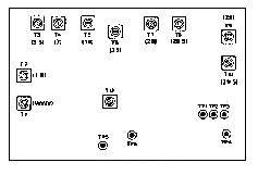
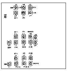
The purpose of this bulletin is to give a simplified alignment procedure for the TS-820 and TS-820S transceivers. We have tried to combine some of the step and rearranged the sequence of step so the alignment may be done quicker. This may be used in lieu of the alignment procedure in the Service Manual.
- Adjustment, A.V.R. unit (X49-1080-00)
- Adjust VR1 for 3.3V
- Adjust VR4 for 9V.
- Adjustment, V.C.O unit (X50-1330-00)
- PLace ST to TONE and connect a frequency counter tp TP5.
- Adjust T1-T11 for proper frequency. (See table)
Note: I'm not sure about the data in the table are correct, because the drawing i read from was very bad.

| Band | Coil | Frequency |
|---|
| WWV | T1 | 24.08 MHz |
| 1.5 | T2 | 10.88 MHz |
| 3.5 | T3 | 12.88 MHz |
| 7 | T4 | 16.08 MHz |
| 14 | T5 | 23.08 MHz |
| 21 | T6 | 30.08 MHz |
| 28 | T7 | 37.08 MHz |
| 28.5 | T8 | 37.58 MHz |
| 29 | T9 | 28.08 MHz |
| 29.5 | T10 | 28.58 MHz |
| AUX | T11 | Received signal
+ 0.03 MHz |
- Adjustment of coil pack (X44-1140-00)
- Turn screen grid (S.G.) switch (rear panel) OFF, heater switch ON.
- Center DRIVER control.
- Peak coil pack all bands for max. reading on panel meter in TX and RX (except WWV in TX).
Another note: I'm not sure about the data in the table are correct, because the drawing i read from was very bad.

Adjustment
sequency | Band | VFO meate |
|---|
| 1 | 1.8 | 100 |
| 2 | 3.5 | 250 |
| 3 | 7 | 150 |
| 4 | 14 | 175 |
| 5 | WWV | 0 : 15.0 MHz |
| 6 | 21 | 225 |
| 7 | 28.5 | 500 |
- Carrier point (X50-1310-00)
- Peak TX power in CW mode. Then switch to LSB and modulate with Audio Gen. (A.G.) @ 5 mv 1500Hz while reducing mic. gain to 500 Watts outputs.
- In the CW mode connect a frequency counter to TP5 on the IF unit (X48-1150-00) and adjust TC1 on the CAR-2 Unit (X50-1320-00) for 8.830.7 MHz.
- Adjust VR1 o the CAR-1 Unit (X50-1310-00) for equal output freq. on USB and LSB.
- In LSB mode, check the RX and TX frequency at TP5 on the IF Unit. It should not change.
- With mode switch in LSB position Audio Gen. input @ 5mv, vary input frequency from 400Hz to 2600Hz and check for BALANCED output while monitoring on scope LSB to USB and vice versa.
- Speech processor (X48-1150-00)
- Tune TX for maximum output power at 14.175 MHz.
- Set mic. gain in center and S.G. off, comp meter ON.
- Place scope on TP2 and counter on TP3.
- Set A.G. for 10mv @ 1500Hz and modulate unit.
- Turn processor max. "ON" position, and adjust TC4 to 451.9 ± 200 Hz.
Adjust T11, T12, T13 for peak indication on COMP. meter.
- Peak T14 by scope on TP2.
- Turn processor full C.C.W.. and reduce A.G. gain to 1mv @ 400Hz.
- Adjust TC4 for max. level n scope but at proper frequency. (451.9 ± 200Hz) (May adjust slightly off frequency if higher peak can be obtained.)
- Sweep A.G. frequency from 400Hz to 2000Hz and check for balanced output on LSB and USB.
- COMP. full clockwise and @ 1500Hz adjust TC3 and VR6 for min. reading on COMP. meter.
- At 1500Hz @ 10mv adjust VR7 to balance processor in "ON" and "OFF" positions (same level).
- Balance mod. adjustment (X48-1150-00)
- In CW position adjust TX for max. output. Key unit with mode switch in SSB position (no Mod.).
- Adjust VR5 and TC2 for min. output level on scope.
- Check BALANCED output LSB and USB.
- Neutralization
- S.G. switch turned off after TX has been tuned in CW mode at 21.3MHz.
- Adjust neutralization cap in final cage for min. output as seen on scope.
|
