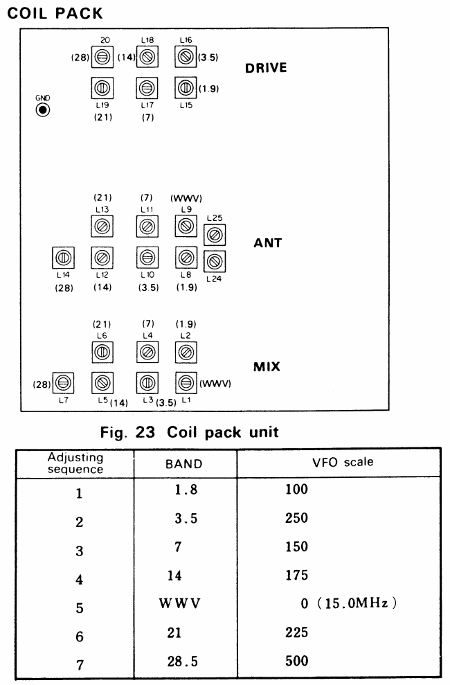
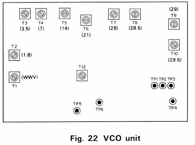
The following information is for the installation and alignment of the AUX band inthe TS-820. This extra band will be for receive only. Reference will be made to schematics and board layouts as shown in the Service Manual.
Installation
- Remove the top and bottom covers.
- Remove the Connectors from the PLL Assembly.
- Remove the PLL assembly and set it aside.
- Use the board layout of the Coil Pack to locate thepositions for the ANT and MIX coils on the Coil Pack.
- Install the ANT and MIX coils on the Coil Pack.
- Remove both covers from the PLL Assembly.
- Remove the 5 Phillips head screws holding the PD Unit in the PLL assembly and carefully remove the PD unit.
- Use the board layout of the PD unit to locate Q11.
- Install R01, R02, C01, C02 and X01 as needed for the band desired.
- Locate terminals AUX, B1, B2, B3, and B4 on the PD unit.
- Install a jumper from the AUX terminal to the B terminal for the band desired. B1 is for 1.8 MHz to 9 MHz, B2 is for 10MHz to 18MHz, B3 is for 19MHz to 24MHz and B4 is for 25MHz to 30MHz.
- Replace the PD unit in the PLL Assembly.
- Use a 3mm nutdriver to remove the 4 hex nuts mounting the VCO unit in the PLL assembly, then remove the two phillips screws.
- Carefully remove the VCO unit from the PLL assembly.
- Use the board layout of the VCO unit to locate Q11.
- Install C01, C02, C03, C04, C05, and T11 as needed for the band desired. Install T11 last.
- Replace the VCO unit in the PLL assembly.
- Install the connectors on the PLL assembly.
Alignment
- Turn on the TS-820.
- Tune VFO to 250.
- Set band switch to AUX.
- Set the TUN/NOR switch on the VCO unit to TUN.
- Connect a frequency counter to terminals TP5 and TP6 on the VCO unit. (TP6 is ground).
- Adjust T11 for a frequency of 9.08 MHz plus the lower limit of the band desired.
- Connect a frequency counter to TP4 and ground on the PD unit, and verify the frequency of the reference oscillator. It may vary +/- 500KHz.
- Return the TUN/NOR switch on the VCO Unit to the NOR position.
- Turn off the TS-820S.
- Replace the covers on the PLL assembly and reinstall it in the transceiver.
- Replace the top and bottom covers on the TS-820S.


Caution
Do no use magnetized tools when working on the PLL assembly. Beryllium
tools would be better than ferrous ones. If the PLL assembly should become
magenetized, use a bulk tape eraser on open core AC transformer to
demagnetize it.
|
