In August 2001 I bought a new Kenwood TS-2000X transceiver. I had fallen in love with it from the QST review and had heard glowing reports from other owners. So although I had a brand new Yaesu FT-847, I went ahead and got the TS-2000 too.
My station was already set up to use separate receive feedlines for every band, so before I ever powered up the TS-2000 I opened it up and modified the 144 and 432 sections to provide coaxial inputs indepent from the main connector for each band. The original connector is then used only for the transmit signal. But for the 1296 band it was not so easy to see how to separate and I did not get around to figuring out how to do it until recently (June 2003). There are many advantages to setting up a station this way and I will outline some of these things in the future, but for now I just want to show how I made the modifications.
Separate Receive Inputs for the TS-2000X
For 2 meters and 432 Mhz, the changes are simple and do not involve any electrical or mechanical changes to the TS-2000. For the 1296 band a trace must be cut and two solder connections to the board must be made.
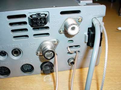
Here is a picture of the back of the modified TS-2000X, showing the three new coaxial inputs.
The wires come out through existing holes in the TS-2000 chassis. Each input is terminated with a BNC connector.
Note that the two meter input is wrapped around the two slots to provide strain relief.
Taking the Rig apart Opening the TS-2000 to make the 144 or 432 mods requires the bottom cover to be removed.
Turn the rig upside down and remove the bottom cover. the PC board that you now see must be partially removed. You need to unplug one coax plug and remove the 17 tapping screws that hold down the board, and remove the ground clip on the right hand edge (see second picture below):
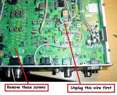
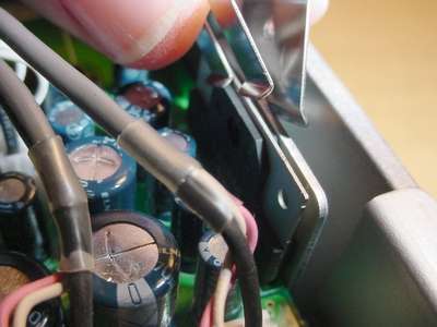
Removing the ground clip.
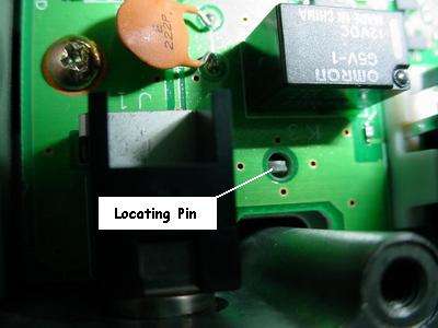
Once all 17 screws are removed, gently lift the board from the front until it is high enough to clear the locating pin at the rear of the board, shown below, and then slide the board forward until the connectors protruding through the rear panel are clear and the rear of the board can be raised.
Once the rear is free, lift the board from the rear and carefully turn it upside down, towards the front. All the wiring at the front of the board is loose enough so you will not have to disconnect any of it. Here is the board being removed:
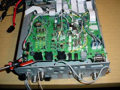
Next remove the metal shield that is below the board (10 screws):
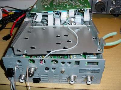
Here is the TS-2000 with the bottom board removed and ready to make the modifications:
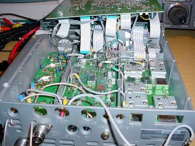
Making the 144 and 432 Mods
The input connectors to the 144 and 432 receiver RF sections are next to each other in the center compartment of the rig. Each one has a coaxial jumper that goes through the center shield to the left hand compartment (as viewed in the pictures). I removed the short jumper used on 432 and saved it for reinstallation later if I want to undo this change. The two meter jumper was insulated and left hanging (see the picture below).
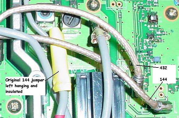
If you can find suitable plugs to match the RF jacks on the board you can use them. I made my own as shown below:
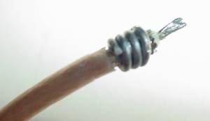
The center pin is enlarged and stiffened by soldering a short piece of solid bare wire alongside the stranded center conductor. Slightly larger solid bare wire (about #22) was wound around the shield and soldered in place to match the size of the jack that it plugs into. It only takes about a minute to make a connector like this and it works just fine.
Here is the inside of the modified TS-2000 showing all the 144 and 432 changes.
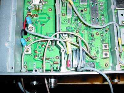
I neglected to make the 432 line long enough to wrap it for a strain relief. So far I've had no trouble with it but I can always do it over if it breaks.
This completes the 144 and 432 mods. Put the TS-2000 back together (except for the covers if you are going to do the 1296 mod too).
Making the 1296 Modifications
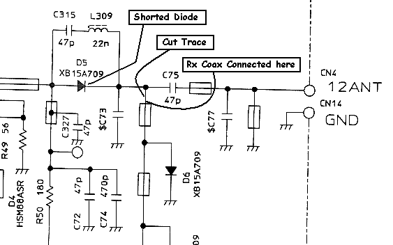
The antenna switching in the 1296 module does not use relays or jumpers, but rather is diode switched. To convert to a separate receive antenna input it is necessary to cut a trace to isolate the receiver from the transmitter, short out the transmit RF path switching diode, and solder a small piece of coax to the circuit board.
Remove the top and bottom covers and the side cover from the 1296 module. Below are pictures of the inside modifications:
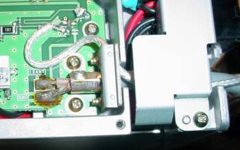
The trace is cut between the capacitor marked S1 and where the center conductor of the coax is soldered on.
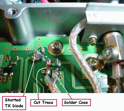
The TX diode is shorted out by a small piece of copper foil soldered across it.
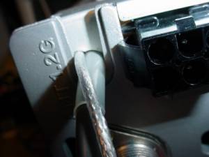
Remove the bracket shown in the upper picture and grind a small hollow into the upper side of the hole where the transmit feedline exits. Smooth the edges so it cannot cut your coax and clamp it back down over your new RX coax. Make it tight to provide strain relief. Here is the outside view:
Below is the schematic of the output portion of the 1296 module, showing the changes you have now made:
|
