Kenwood TS-950S (TS 950 S TS950S) mods reviews software and diagrams


ham | what is new | links
 Welcome to Www.Hampedia.net  submit to reddit
29 March 2024, 13:48 UTC 


SDR


ELAD
SDRplay

Transceivers


Kenwood
Midland
Yaesu
Alinco
Icom
Other

Antennas


M2
Par
Gap
Sirio
Araki
Maco
Nil-Jon
Maldol
Comet
Hustler
Nagoya
Watson
Hy-Gain
Dressler
Cue Dee
Solarcon
Diamond
Cushcraft
Quicksilver
Moonraker

Power supplies


Powerbox
Kenwood
Diamond
Samlex
Mascot
Daiwa
Yaesu
Alinco
Icom
H&H

Rotators


M2
CDE
Yaesu
Create
Kenpro

Antenna tuners


MFJ
LDG
SGC
Icom
Yaesu
Mizuho
Dentron
Kenwood
Sommerkamp
Barker & Williamson

Repeaters


GME
Icom
Zodiac
Kenwood

Transverters


Microwave Modules
Tokyo Hy-Power
SSB Electronics
Tecnostudi
Kenwood
Yaesu
Minix

Meters


Diamond
Comet
Bird
MFJ

Ham resources


Propagation:
  Sporadic E skip (Es)
  Backscatter
  Tropo
  Meteor Scatter (MS)
  F2 Skip
  Aurora
  Trans-equatorial scatter (TE)
  Lightning scatter (LS)

Kenwood TS-950S (TS 950 S TS950S)
TS-950S
Programming interface schematics for Kenwood :
Programming software for Kenwood TS-950S (TS 950 S TS950S) :
PDF User Manual for Kenwood TS-950S (TS 950 S TS950S) :
PDF Service Manual/schematics for Kenwood TS-950S (TS 950 S TS950S) :

Mods for Kenwood TS-950S (TS 950 S TS950S) :
   Kenwood TS-950S (TS 950 S TS950S) W6NL Keying Jitter Correction Circuit
   Kenwood TS-950S (TS 950 S TS950S) Carrier Adjustment
   Kenwood TS-950S (TS 950 S TS950S) Antenna Tuner modification
   Kenwood TS-950S (TS 950 S TS950S) Using Subreceiver to Improve TS-950 Noise Blanker
   Kenwood TS-950S (TS 950 S TS950S) SO2 Adjust
   Kenwood TS-950S (TS 950 S TS950S) Implementation of the K6XX QSK Waveform Mod
   Kenwood TS-950S (TS 950 S TS950S) RF gain mod
   Kenwood TS-950S (TS 950 S TS950S) Countermeassure against cold solder joint at the resistor block; CP1-CP4 in the PLL unit
   Kenwood TS-950S (TS 950 S TS950S) Hum with monitor ON
   Kenwood TS-950S (TS 950 S TS950S) Noise with Sub-Band noise blanker ON
   Kenwood TS-950S (TS 950 S TS950S) 14.200 MHz transmit spur
   Kenwood TS-950S (TS 950 S TS950S) Low power output after temp. protection
   Kenwood TS-950S (TS 950 S TS950S) Infinite SWR at beginning of transmission
   Kenwood TS-950S (TS 950 S TS950S) Smoke from antenna tuner unit
   Kenwood TS-950S (TS 950 S TS950S) Transmit spur
   Kenwood TS-950S (TS 950 S TS950S) 18.115 MHz spur
   Kenwood TS-950S (TS 950 S TS950S) TX image on 18.115 MHz
   Kenwood TS-950S (TS 950 S TS950S) 80 meter spurious emission
   Kenwood TS-950S (TS 950 S TS950S) Final bias circuit change
   Kenwood TS-950S (TS 950 S TS950S) Rear panel cooling fan
   Kenwood TS-950S (TS 950 S TS950S) Speech processor noise
   Kenwood TS-950S (TS 950 S TS950S) N.B. Gate switching noise
   Kenwood TS-950S (TS 950 S TS950S) Early protection with TL-922A
   Kenwood TS-950S (TS 950 S TS950S) RX digital noise
   Kenwood TS-950S (TS 950 S TS950S) Two second TX power delay with MONI on
   Kenwood TS-950S (TS 950 S TS950S) Receiver noise
   Kenwood TS-950S (TS 950 S TS950S) general coverage transmit mod
   Kenwood TS-950S (TS 950 S TS950S) Power On Funktions
   Kenwood TS-950S (TS 950 S TS950S) Front-panel Sidetone Level Control

Kenwood TS-950S (TS 950 S TS950S) technical specifications :  Kenwood TS-950S (TS 950 S TS950S) technical specifications


Kenwood TS-950S (TS 950 S TS950S) Implementation of the K6XX QSK Waveform Mod

This article describes the specific steps required to implement this mod in the Kenwood TS-950SD, and assumes that the PC board design referenced above has been used to produce a PC board, and that the PC board has been populated with the required components.

READ THESE INSTRUCTIONS COMPLETELY BEFORE YOU HEAT UP THE SOLDERING IRON.

REFER TO THE SCHEMATICS IN YOUR TS-950xx MANUAL TO CONFIRM
ALL CONNECTIONS BEFORE YOU ATTACH ANY WIRES TO A PC BOARD.

Step-by-Step Installation steps

  1. Remove the top and bottom covers of the TS-950SD and set them aside. Don't forget to disconnect the two cables from the DSP unit before removing the bottom cover of the radio.

  2. Place a protective 'blanket' or other soft material beneath the front of the TS-950SD, so that when the radio is moved and turned, you will not damage the finish on the plastic portion of the front panel.

  3. On each sides of the TS-950SD chassis, just behind the front panel, you will find two Phillips-head screws which hold the front panel in place. The bottommost of the two screws, when loosened 2-3 turns. acts as a hinge for that side of the front panel, allowing it to first slide forward about 1-1/2 inches and then to tilt forward to expose the back of the front panel and the front of the sub-front panel PC boards mounted to the main chassis. The topmost of the two screws may be completely removed to allow the front panel to move. Loosen the bottom screws, remove the top screws and slide the front panel forward.
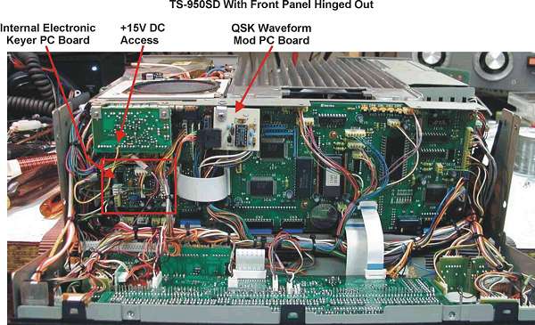
    Figure 1
    Figure 1


  4. IN THE STEP WHICH FOLLOWS, BE CAREFUL TO NOT ALLOW THE FRONT PANEL TO 'FLOP' DOWN IN AN UNCONTROLLED MANNER. Should this happen, one or both of the thin white ribbon cables just to the right of center in Figure 1 may become unplugged and will require reinstallation. In this case, you must CAREFULLY pry out on the locking tabs which hold the locking mechanism of the socket and then lift the mechanism about 1/4" in order to be able to re-insert the ribbon cable. Once the cable is reinserted, press the locking mechanism back into place.

  5. Slide the entire radio forward, such that the front of the radio extends off the front edge of the work surface, allowing the front panel to rotate from its normal vertical position to a horizontal position. If necessary, take steps to support the front panel at an angle no greater than 90° to the vertical.
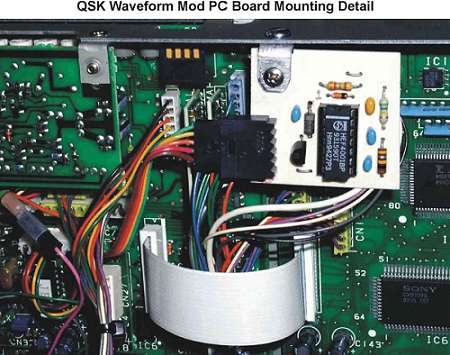
  6. Figure 2
    Figure 2
    Prepare a 6" length of 5-conductor cable to attach to the 5-pin connector on the PC board. Note that the wires for the GND, QSK, and Key Out lines will be connected to the BACK side of the TS-950SD internal Keyer PC board, while the +V and the Key In pins of the 5-pin connector must be connected to other off-board devices. As such, the +V and AUX Key In wires should be cut to 3"-4" and terminated with single-pin receptacles or pins. AMP AmpModu 0.25" pins, receptacles, and housings (Mouser 571-1021073, 571-875236, and 571-7874992) work well for this task. Use a single-pin receptacle and housing on the AUX Key In lead, and a single pin (insulated with heat-shrink-tubing) on the +V lead. The mating connections will be used on the leads coming from the external sources. Note that I added a slightly larger diameter heat-shrink tubing 'cover' to provide additional protec-tion for the single pin connection, allowing the heatshrink tubing to slip over the single-pin housing, thus protecting the single pin lead when it s not inserted into the mating single-pin housing receptacle. This added protection can be seen in the photo above, connected to the pink wire, in the lower left quadrant of the picture. See a better example a bit later in this article when the connection of the AUX Key Input is connected to the ACC2 connector.
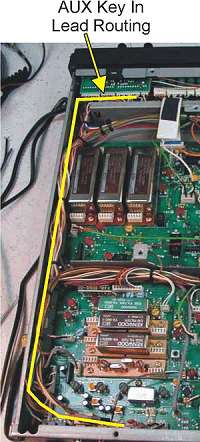
  7. Figure 3
    Figure 3
    Mount the QSK mod PC board to the underside of the top lip of the chassis front, as shown in Figure 2 above, and in Figure 1, on the first page of this document.

  8. To a 26" length of small diameter (#22-#24) insulated wire, attach a single pin, and insulate it in the manner described above, including the oversized heatshrink cover for the housing into which it will plug. Attach this connector to the mating single-pin housing/receptacle coming from the AUX Key In lead of QSK Mod PC board.

  9. Carefully, run the free end of the 28" length of wire between the back of the front panel and the front of the facing PC boards, out the bottom of the TS-950SD.

  10. Carefully fold up front panel, slide it into place, and secure it in place with the two TOP screws. There is no need to tighten the hinge screws at this time.

  11. Carefully invert the TS-950 and turn it so the rear of the radio is now facing the front of your work surface.

  12. Refer to Figure 3, and route the free end of the Key In lead along the side of the chassis, to the rear of the chassis. As you pass the tie-wraps which secure the other wires into bundles, take time to pass this Key In lead through the tie-wraps as well.

  13. When the AUX Key In lead has been properly routed, lay it just inside the back edge of the chassis, measure the length required to attach this lead to pin 2 of the ACC2 connector (see Figure 4). SUBTRACT two inches (2") from the measured length and cut off any excess wire length. To this end, attach a single-pin receptacle and slip it into a single-pin header.

  14. Attach a .001uF (50V min.) cap between pins 2 & 4 of the ACC2 jack as shown in Figure 4.
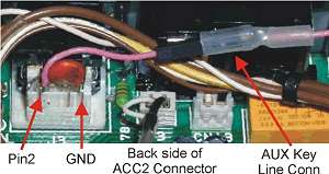
  15. Figure 4
    Figure 4
    From the excess wire cut in step 13, measure and cut a 3" length. Strip 1/8" of insulation from both ends and tin them. On one end, install a Figure 4 single-pin receptacle and slip it into a single-pin housing. Solder the other end of this wire to pin 2 of the ACC2, on the back side of the jack.

  16. To the unterminated end of the AUX Key In lead coming from the front panel, install a single pin and insulate it with heatshrink tubing. Note that the heatshrink tubing is only shrunk at ONE END, the end covering the pin itself is NOT shrunk, to allow insertion of the pin into the mating single-pin housing.

  17. Turn the TS-950SD back around, so the front panel is facing the front of the work surface and tilt the front panel to the horizontal position.

  18. Refer to Figure 1 and locate the internal keyer PC board. This PC board is not screw-mounted. It plugs onto two header blocks attached to the PC board in back of it. To access the keyer PC board, carefully, rock it back and forth as you pull it away from the larger PC board.

  19. The keyer PC board has two (2) multi-wire header connectors attached to it. Carefully remove both of the multi-wire header connectors.
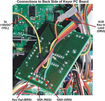
  20. Figure 5
    Figure 5
    Turn the keyer PC board so it's back (foil) side faces you.

  21. Refer to Figure 5. At the bottom of the keyer PC board, there are six (6) pads, each immediately above a matching hole (for the header plug pins). In the following step, pin numbering will begin with the leftmost of these six pads and progress to the right. Wires will be connected to pins 2, 3, & 6, respectively.

  22. Remove 1/8" (max.) of insulation from the three unterminated leads coming from the QSK mod PC board, tin the leads (note: the insulation may recede as the ends are tinned) and clip the tinned leads to a length of 1/8"

  23. Attach the wire from pin 1 (Key Out) on the QSK Mod PC board to pin 2 on the keyer PC board. BE SURE to attach the lead so the rest of the wire faces the INSIDE of the PC board.

  24. Attach the wire from pin 2 (QSK/Full) on the QSK Mod PC board to pin 3 on the keyer PC board.

  25. Attach the wire from pin 5 (GND) on the QSK Mod PC board to pin 6 on the keyer PC board.

  26. Position the keyer PC board so that it can be reinstalled onto the header blocks on its motherboard. Arrange the wires from the QSK mod PC board such that they are well clear of the header holes on the (now) right side of the keyer board, and so they exit from the top rear of the QSK mod PC board. Reinstall the keyer PC board.

  27. Reinstall the two multi-wire header plugs removed from the keyer PC board in step 19, above.
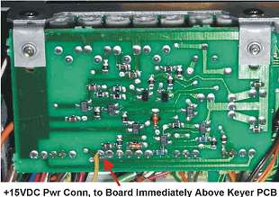
  28. Figure 6
    Figure 6
    Cut a 3" piece of insulated wire (preferably the same color and type of wire as used for the +15VDC (+V) lead coming from the QSK mod PC board 5-pin connector. Strip 1/8" of insulation from each end of this wire and tin both ends. To one end of this wire, attach a single-pin receptacle and insert it into a single-pin housing. This will mate with the single pin plug which was created in step 6 of the instructions.
    Attach the unterminated end of this wire to the +15VDC pad on the PC board immediately above the keyer PC board, see Figures 1 & 6 for the location of the PC board and for the proper pad to connect to. Also, confirm this connection in your TS-950 manual (schematic section).

  29. Connect all of the single-pin connectors to their respective pins (+15VDC, and two connections Figure 6 (front & rear) of the AUX Key In line).

  30. This should complete installation of the QSK Waveform Mod. However, you will still need to tweak the component values for CV and RT, and possibly CT as well. With any luck at all, you won't have to change the value of CT however.

  31. If you installed a 1-Meg PC-mount trimmer pot at RT, skip to step 33.

  32. Temporarily detach the QSK mod PC board from its mounting and tack-solder two 1" leads into the holes reserved for RT and attach a 1-Meg potentiometer (to be referred to as RT during the testing period) to these leads. Reinstall the PC board.

  33. Place a 1/4" stereo plug into the KEY jack (not the AUX Key In connection at ACC2) on the rear of the TS-950. You will NOT be able to send CW via the AUX Key In connection unless the regular KEY jack has a plug in it.

  34. Run the TS-950 output coax run to a dummy load though a monitor scope (or attached to an oscilloscope).

  35. Connect the output of your EXTERNAL CW keyer to the AUX Key Input at ACC2 pin 2 and ground. You may need to use clip leads for this connection until you fabricate a jack to plug into ACC2 pin 2.

  36. Turn the TS-950 on and set the POWER control fully CCW. Set the VOX/PTT switch to VOX, and FULL/SEMI (QSK)to SEMI.

  37. Set the external keyer speed to around 30 WPM and the weighting to 50%.

  38. Send a string of DITs and slowly increase the POWER output control until an output envelope is shown on the monitor scope.

  39. While watching the CW waveform on the scope, adjust the Horizontal Sweep speed of the scope in order to stop two consecutive DITs on the screen.

    HINT: Increase the speed of the Horizontal Sweep, to the point that one DIT wraps itself around the trace and you can then superimpose the BREAK of this DIT on top of the MAKE of the same DIT. There will a bright line through the trace, but you will be able to easily tell if the weighting is correct because a 50% weighting will cause the BREAK to end just as the MAKE begins. If the two overlap, then the weighting is too heavy. If they don't touch, then it's too light.

  40. If the weighting in this mode (SEMI BREAK-IN) is too light, increase the value of CV, if it is too heavy, reduce the value of CV a bit, until you obtain a weighting ratio of approximately 50%.

  41. Set the FULL/SEMI switch to FULL.

  42. While sending a string of DITs, adjust the value of RT until the space between the end of one DIT and the start of the next DIT is the same length as the length of the DIT itself.

  43. Once you have successfully set the weighting, you are finished.

  44. If you did not use a PC-mount pot for RT, you must now remove the temporary pot (and leads), measure the value of the pot, and replace it with a fixed resistor of the same approximate value.

  45. If required, reinstall the QSK mod PC board.

  46. Tilt the front panel back into place (vertical), slide it back toward the main chassis, and secure it in place with two screws at the top, on each side. Retighten (until snug only) the two hinge screws. Replace the top and bottom covers of the radio and reattach the two cables from the DSP unit on the bottom of the radio.

You are done! Whew!


Better QSK Waveforms

TS-950 users note: You must connect to a +15VDC supply line, rather than to a +5VDC line. Otherwise, the VOX/T-R line may trigger falsely. This mod must be used with an AUX Key input. Finally, this mod will NOT function in the TS950 series unless a 1/4" stereo phone plug (empty or otherwise) is installed in the KEY jack an the back panel of the radio.
Capacitors, Connector(s) & Notes

.001 uF monolithic - Mouser 21 RX510
.02uF monolithic - Mouser 21 XR420
0.1 uF monolithic - Mouser 21 XR310

(Optional) 5-Pin .025" Rt-Angle PC-Mtg Shrouded (male) Header connector, Mouser 571-1033613, mating plug is with Mouser 571-1022413 (this mating plug, requires five 571-875236 female receptacles).

You may find it helpful to have a couple single-pin connectors for the DC and the KEY IN lines as well. Mouser 571-7874992 single-pin housings (with 571-875236 receptacles) mate with 571-1021073 push-in pin or with a single pin from Mouser 517-6111 TN.

* Starting value, Cv & CT must be found by trial and error. Start with .001 uF at Cv and increase if non-QSK keying needs to be heavier.

For CT, start with .02uF-.022uF and about 500k for RT. Or use a 1 M pot at RT and adjust it until the proper weighting is achieved. Then replace the pot with a fixed resistor of equal value. Note that pads are also provided for a permanently mounted trimpot (Mouser 72-T7RYB-1 M or 594-75H-1 M), if you wish to replace RT with a variable device altogether.

Click to view full size. (225 Kb)

Foil-Side of PC board, showing X-Ray view of component placement. All components mount an the NON-FOIL side of board.


More Kenwood Radioamateur Transceivers

Kenwood VHF/UHF Handhelds:
    Kenwood TH-D7AG (TH D7 AG THD7AG) service manual and specs
    Kenwood TH-D7E (TH D7E THD7E) service manual and specs
    Kenwood TH-D72A (TH D72A THD72A) service manual and specs
    Kenwood TH-D72E (TH D72E THD72E) service manual and specs
    Kenwood TH-F6A (TH F6A THF6A) service manual and specs
    Kenwood TH-F7E (TH F7E THF7E) service manual and specs
    Kenwood TH-G71E (TH G71E THG71E) service manual and specs
    Kenwood TH-K2AT (TH K2 AT THK2AT) service manual and specs
    Kenwood TH-K2E (TH K2E THK2E) service manual and specs
    Kenwood TH-K2ET (TH K2ET THK2ET) service manual and specs
    Kenwood TH-K4E (TH K4E THK4E) service manual and specs
    Kenwood TH-K7 (TH K7 THK7) service manual and specs
    Kenwood TH-21AT (TH 21AT TH21AT) service manual and specs
    Kenwood TH-21E (TH 21E TH21E) service manual and specs
    Kenwood TH-22E (TH 22E TH22E) service manual and specs
    Kenwood TH-25AT (TH 25AT TH25AT) service manual and specs
    Kenwood TH-25E (TH 25E TH25E) service manual and specs
    Kenwood TH-26E (TH 26E TH26E) service manual and specs
    Kenwood TH-27E (TH 27E TH27E) service manual and specs
    Kenwood TH-28E (TH 28E TH28E) service manual and specs
    Kenwood TH-41E (TH 41E TH41E) service manual and specs
    Kenwood TH-42E (TH 42E TH42E) service manual and specs
    Kenwood TH-45AT (TH 45AT TH45AT) service manual and specs
    Kenwood TH-45E (TH 45E TH45E) service manual and specs
    Kenwood TH-46E (TH 46E TH46E) service manual and specs
    Kenwood TH-47E (TH 47E TH47E) service manual and specs
    Kenwood TH-48E (TH 48E TH48E) service manual and specs
    Kenwood TH-55E (TH 55E TH55E) service manual and specs
    Kenwood TH-59 (TH 59 TH59) service manual and specs
    Kenwood TH-75E (TH 75E TH75E) service manual and specs
    Kenwood TH-77A (TH 77A TH77A) service manual and specs
    Kenwood TH-77E (TH 77E TH77E) service manual and specs
    Kenwood TH-78E (TH 78E TH78E) service manual and specs
    Kenwood TH-79E (TH 79E TH79E) service manual and specs
    Kenwood TH-89 (TH 89 TH89) service manual and specs
    Kenwood TH-205E (TH 205E TH205E) service manual and specs
    Kenwood TH-215E (TH 215E TH215E) service manual and specs
    Kenwood TH-405E (TH 405E TH405E) service manual and specs
    Kenwood TH-415E (TH 415E TH415E) service manual and specs
    Kenwood TR-2200A (TR 2200A TR2200A) service manual and specs
    Kenwood TR-2200G (TR 2200G TR2200G) service manual and specs
    Kenwood TR-2200GII (TR 2200GII TR2200GII) service manual and specs
    Kenwood TR-2200GX (TR 2200GX TR2200GX) service manual and specs
    Kenwood TR-2200 (TR 2200 TR2200) service manual and specs
    Kenwood TR-2300 (TR 2300 TR2300) service manual and specs
    Kenwood TR-2400 (TR 2400 TR2400) service manual and specs
    Kenwood TR-2500 (TR 2500 TR2500) service manual and specs
    Kenwood TR-2600E (TR 2600 E TR2600E) service manual and specs
    Kenwood TR-3200 (TR 3200 TR3200) service manual and specs
    Kenwood TR-3500 (TR 3500 TR3500) service manual and specs
    Kenwood TR-3600 (TR 3600 TR3600) service manual and specs

Kenwood Mobile VHF/UHF Transceivers:
    Kenwood TM-D700A (TM D700A TMD700A) service manual and specs
    Kenwood TM-D700E (TM D700E TMD700E) service manual and specs
    Kenwood TM-G707E (TM G707E TMG707E) service manual and specs
    Kenwood TM-V7A (TM V7A TMV7A) service manual and specs
    Kenwood TM-V7E (TM V7E TMV7E) service manual and specs
    Kenwood TM-V708 (TM V708 TMV708) service manual and specs
    Kenwood TM-V708A (TM V708A TMV708A) service manual and specs
    Kenwood TM-201A (TM 201A TM201A) service manual and specs
    Kenwood TM-211E (TM 211E TM211E) service manual and specs
    Kenwood TM-221E (TM 221E TM221E) service manual and specs
    Kenwood TM-231E (TM 231E TM231E) service manual and specs
    Kenwood TM-241E (TM 241E TM241E) service manual and specs
    Kenwood TM-251E (TM 251E TM251E) service manual and specs
    Kenwood TM-255E (TM 255E TM255E) service manual and specs
    Kenwood TM-261A (TM 261A TM261A) service manual and specs
    Kenwood TM-271A (TM 271 A TM271A) service manual and specs
    Kenwood TM-401A (TM 401A TM401A) service manual and specs
    Kenwood TM-411E (TM 411E TM411E) service manual and specs
    Kenwood TM-431E (TM 431E TM431E) service manual and specs
    Kenwood TM-441E (TM 441E TM441E) service manual and specs
    Kenwood TM-451E (TM 451E TM451E) service manual and specs
    Kenwood TM-455E (TM 455E TM455E) service manual and specs
    Kenwood TM-461A (TM 461A TM461A) service manual and specs
    Kenwood TM-521A (TM 521A TM521A) service manual and specs
    Kenwood TM-531E (TM 531E TM531E) service manual and specs
    Kenwood TM-541 (TM 541 TM541) service manual and specs
    Kenwood TM-631A (TM 631A TM631A) service manual and specs
    Kenwood TM-642 (TM 642 TM642) service manual and specs
    Kenwood TM-701E (TM 701E TM701E) service manual and specs
    Kenwood TM-702E (TM 702E TM702E) service manual and specs
    Kenwood TM-721A (TM 721A TM721A) service manual and specs
    Kenwood TM-721E (TM 721E TM721E) service manual and specs
    Kenwood TM-731A (TM 731A TM731A) service manual and specs
    Kenwood TM-731E (TM 731E TM731E) service manual and specs
    Kenwood TM-732A (TM 732A TM732A) service manual and specs
    Kenwood TM-732E (TM 732E TM732E) service manual and specs
    Kenwood TM-733E (TM 733E TM733E) service manual and specs
    Kenwood TM-741E (TM 741E TM741E) service manual and specs
    Kenwood TM-742E (TM 742E TM742E) service manual and specs
    Kenwood TM-833S (TM 833S TM833S) service manual and specs
    Kenwood TM-842 (TM 842 TM842) service manual and specs
    Kenwood TM-941A (TM 941A TM941A) service manual and specs
    Kenwood TM-942 (TM 942 TM942) service manual and specs
    Kenwood TM-2400 (TM 2400 TM2400) service manual and specs
    Kenwood TM-2550E (TM 2550E TM2550E) service manual and specs
    Kenwood TR-50 (TR 50 TR50) service manual and specs
    Kenwood TR-751A (TR 751A TR751A) service manual and specs
    Kenwood TR-751E (TR 751E TR751E) service manual and specs
    Kenwood TR-851E (TR 851E TR851E) service manual and specs
    Kenwood TR-7100 (TR 7100 TR7100) service manual and specs
    Kenwood TR-7200G (TR 7200G TR7200G) service manual and specs
    Kenwood TR-7400A (TR 7400A TR7400A) service manual and specs
    Kenwood TR-7500 (TR 7500 TR7500) service manual and specs
    Kenwood TR-7600 (TR 7600 TR7600) service manual and specs
    Kenwood TR-7730 (TR 7730 TR7730) service manual and specs
    Kenwood TR-7800 (TR 7800 TR7800) service manual and specs
    Kenwood TR-7850 (TR 7850 TR7800) service manual and specs
    Kenwood TR-7930 (TR 7930 TR7930) service manual and specs
    Kenwood TR-7950 (TR 7950 TR7950) service manual and specs
    Kenwood TR-8300 (TR 8300 TR8300) service manual and specs
    Kenwood TR-8400 (TR 8400 TR8400) service manual and specs
    Kenwood TR-9000 (TR 9000 TR9000) service manual and specs
    Kenwood TR-9130 (TR 9130 TR9130) service manual and specs
    Trio TR-9300 (TR 9300 TR9300) service manual and specs
    Kenwood TR-9500 (TR 9500 TR9500) service manual and specs
    Kenwood TS-60S (TS 60S TS60S) service manual and specs
    Kenwood TW-4000A (TW 4000A TW4000A) service manual and specs
    Kenwood TW-4100E (TW 4100E TW4100E) service manual and specs
    Kenwood TM-V71A (TM V71A TMV71A) service manual and specs
    Kenwood TM-D710A (TM D710A TMD710A) service manual and specs
    Kenwood TM-V71E (TM V71E TMV71E) service manual and specs
    Kenwood TM-281A (TM 281A TM281A) service manual and specs

Kenwood Base VHF/UHF:
    Trio TR-2E (TR 2 E TR2E) service manual and specs
    Kenwood TS-600 (TS 600 TS600) service manual and specs
    Kenwood TS-700A (TS 700 A TS700A) service manual and specs
    Kenwood TS-700G (TS 700 G TS700G) service manual and specs
    Kenwood TS-700S (TS 700 S TS700S) service manual and specs
    Kenwood TS-711E (TS 711 E TS711E) service manual and specs
    Kenwood TS-770 (TS 770 TS770) service manual and specs
    Kenwood TS-780 (TS 780 TS780) service manual and specs
    Kenwood TS-790E (TS 790 E TS790E) service manual and specs
    Kenwood TS-811E (TS 811 E TS811E) service manual and specs

Kenwood HF and More Transceivers:
    Kenwood TS-50S (TS 50 S TS50S) service manual and specs
    Kenwood TS-120S (TS 120 S TS120S) service manual and specs
    Kenwood TS-120V (TS 120 V TS120V) service manual and specs
    Kenwood TS-130S (TS 130 S TS130S) service manual and specs
    Kenwood TS-130V (TS 130 V TS130V) service manual and specs
    Kenwood TS-140S (TS 140 S TS140S) service manual and specs
    Kenwood TS-180S (TS 180 S TS180S) service manual and specs
    Kenwood TS-430S (TS 430 S TS430S) service manual and specs
    Kenwood TS-440S (TS 440 S TS440S) service manual and specs
    Kenwood TS-450S (TS 450 S TS450S) service manual and specs
    Kenwood TS-480 (TS 480 TS480) service manual and specs
    Kenwood TS-510 (TS 510 TS510) service manual and specs
    Kenwood TS-515 (TS 515 TS515) service manual and specs
    Kenwood TS-520S (TS 520 S TS520S) service manual and specs
    Kenwood TS-520SE (TS 520 SE TS520SE) service manual and specs
    Kenwood TS-530S (TS 530 S TS530S) service manual and specs
    Kenwood TS-570DG (TS 570 DG TS570DG) service manual and specs
    Kenwood TS-570S (TS 570 S TS570S) service manual and specs
    Kenwood TS-660 (TS 660 TS660) service manual and specs
    Kenwood TS-670 (TS 670 TS670) service manual and specs
    Kenwood TS-680S (TS 680 S TS680S) service manual and specs
    Kenwood TS-690S (TS 690 S TS690S) service manual and specs
    Kenwood TS-820 (TS 820 TS820) service manual and specs
    Kenwood TS-820S (TS 820 S TS820S) service manual and specs
    Kenwood TS-830S (TS 830 S TS830S) service manual and specs
    Kenwood TS-850S (TS 850 S TS850S) service manual and specs
    Kenwood TS-870S (TS 870 S TS870S) service manual and specs
    Kenwood TS-900 (TS 900 TS900) service manual and specs
    Kenwood TS-930S (TS 930 S TS930S) service manual and specs
    Kenwood TS-940S (TS 940 S TS940S) service manual and specs
    Kenwood TS-950S (TS 950 S TS950S) service manual and specs
    Kenwood TS-950SDX (TS 950 SDX TS950SDX) service manual and specs
    Kenwood TS-2000 (TS 2000 TS2000 TS-2000X TS-B2000) service manual and specs
    Kenwood TS-590S (TS 590 S TS590S) service manual and specs
    Kenwood TS-990S (TS 990 S TS990S) service manual and specs

Kenwood Transmitters:
    Kenwood T-599D (T 599D T599D) service manual and specs
    Trio TX-310 (TX 310 TX310) service manual and specs
    Kenwood TX-599 (TX 599 TX599) service manual and specs
    Kenwood TX-599 Custom Special (TX 599 Custom Special TX599 Custom Special) service manual and specs


CB Equipment


President
Midland
Uniden
Zodiac

 Power amplifiers


Beko
Icom
Alinco
Drake
Yaesu
Daiwa
Collins
Kenwood
DanAmps
Ameritron
Autophon
Eto/Alpha
Command Technologies
E.F.Johnson
Dentron Radio Co.

FRS/GMRS


Bell
GPX
ENC
Tekk
Icom
Sony
Alinco
Drake
Cobra
Maxon
Vertex
Conair
Uniden
Jenson
Ranger
Midland
Whistler
Magnum
Unwired
Coleman
Motorola
Audiovox
Memorex
Columbia
Samsung
Standard
Kenwood
Cherokee
Panasonic
Freetalker
Vtech Vtalk
RadioShack
Fanon Courier
Sharper Image
General Electric
Oregon Scientific

PMR446


Sommerkamp
FreeQuency
Goodmans
Kenwood
Lafayette
President
Binatone
Motorola
Multicom
Albrecht
Maycom
Topcom
Xtreme
Ondico
Telcom
Maxon
Vertex
Zodiac
Yaesu
Cobra
Alinco
Icom
Alan
ITT