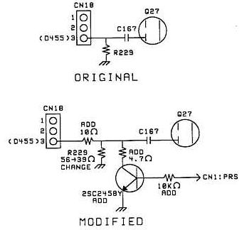
When the Processor-In control is set to some level below 10 dB of compression, a crackling noise can be induced on the transmit signal. The following modification will reduce the noise. After the modification has been performed, the noise can only be heard when the Processor-In control is set too low to be functional.
Note: This modification has already been performed on models starting with serial number 0120441.
Required parts:
Transistor (PNP)                      (2SC2458Y)
4.7 ohm, 1/6 watt resistor            (RD14CB2C4R7J)
10 ohm chip resistor                  (RK73FB2A100J)
39 ohm chip resistor                  (RK73FB2A390J)
10 Kohm chip resistor                 (RK73FB2A103J)
- Disconnect the power cord and antenna.
- Remove the top and bottom covers (18 screws).
- Locate the Signal board on the bottom of the transceiver. This is the front right board of the 4 boards on the bottom of the transceiver.
- Disconnect the 3 flex cables and remove the 6 mounting screws from the Signal board.
- Carefully lift the board and rotate it toward the AF unit (front left board) to expose the foil side of the Signal board. Loosen the wire harness as necessary to rotate the board.
The following will be performed on the foil side of the Signal board.
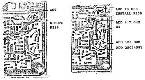
- Cut the foil between pin 3 of CN18 and chip resistor R229.
- Desolder and remove R229.
- Solder a 10 ohm chip resistor across the cut foil.
- Solder a 39 ohm chip resistor in place of R229 (it will be slightly offset due to the installation of the 10 ohm resistor).
- Solder a 4.7 ohm resistor to the collector of a 2SC2458(Y) transistor. Shorten the lead length to accommodate the following installation and insulate the leads with shrink tubing.
- Solder the exposed end of the 4.7 ohm resistor to chip capacitor C167.
- Solder the base and emitter leads as shown in the accompanying diagram.
- Solder a 10 Kohm resistor to the circuit as shown.
 
This modification is covered under the 1 year warranty.
Time required to perform the modification is 1 hour or less.
|
